The introduction of wireless networks has reduced the costs and effort of installing cables throughout the buildings. Wireless networks works on radio waves to connect to various devices to provide internet services. This implementation is done at the physical layer of the OSI model network structure. There are a number of advantages of using wireless networks including convenience, mobility, productivity, easy setup, expandable, security, less cost, etc.
Different types of wireless networks can be established as per requirement including Wireless personal area networks (WPAN) which Interconnects devices in a short span, Wireless local area network (WLAN) which extends within a building or campus, wireless metropolitan area networks (WMAN) which are spread over a city and Wireless wide area networks (WWAN)which is worldwide. In order to power these networks wireless broadband routers are used. Other equipment for setting up a wireless network includes switches, wireless access points, print servers, game adapters, and so on. For larger applications, external adapters and range extenders are also used.
A wireless network also faces a lot of difficulties like interferences from other networks or equipment generating radio waves, absorption of electromagnetic waves or reflection, hidden node problem, etc. While placing it, one must position the wireless router off the floor and away from walls and metal objects to use its full strength. One important factor while installing wireless network is security as its signal can be easily broadcasted outside the premises. Wireless networks have a network security key to guard them from illegal access. There are also encryption techniques to protect the data from going into unauthorised hands.
This section discusses the devices and techniques of managing the communication between dissimilar networks. They help in realising the best way to transmit data when the network poses different kinds of difficulties.
Routing Table
Apart from communicating within the same network, a need may arise for computers to interact with devices on other networks or subnet. In order to ensure this communication, a router is connected to both the networks. When a packet arrives the router has to take decision about how to send the packet to its destination and what is the best path. This decision can be made either by dynamic routing protocols in which a routing table is automatically created and updated or by static routing in which administrator creates a routing table manually.
To give a clear understanding of the routing table we must tell that a routing table configuration contains the following information:
- Network ID: This is the IP address of the destination.
- Netmask: Used to determine the network ID from the IP address.
- Next hop/Gateway: The IP address where the packet is forwarded.
- Interface: When forwarding the packet to the next hop or destination, it is the outgoing network interface the device should use.
- Metric: It is the cost of each route to select the most cost-effective path.
In this routing table tutorial there are two methods of building a routing table: Static Routing and Dynamic Routing.
Dynamic Routing– For larger and more fluids routes, in order to get more intelligent decisions about selecting the best path, dynamic routing tables are made. Once the routing method is decided, decision about using the right routing protocol for dynamic routing needs to be made. There two main categories of dynamic routing protocol: exterior gateway protocols (EGPs) and interior gateway protocols (IGPs).
EGP is exterior to the network domains and connect multiple network domains. Routing inside these network domains is handled by IGP. The most common EGP is Border Gateway Protocol (BGP). Whereas IGP majorly uses four protocols –
- Open Shortest Path First (OSPF)
- Enhanced Interior Gateway Routing Protocol (EIGRP)
- Intermediate System to Intermediate System (IS-IS)
- Routing Information Protocol (RIP)
Static Routing – Static routing is suitable for very small networks and they cannot be used in large networks. It has no specific routing algorithm. A static routing table is formed, maintained, and updated manually by a network administrator. To ensure full connectivity, a static route to every network must be designed on every router.
Spanning Tree Protocol (STP) – It is a layer 2 protocol and its major aim is to prevent loops when there are redundant paths in the network. It runs on bridges and switches. It works by blocking links in an Ethernet network. Only if active link fails the blocked links can again be brought into service. Recalculations are performed automatically by spanning tree during network change. STP generates a spanning tree within a network of connected layer-2 bridges, and deactivates those associations that are not part of the spanning tree, allowing a single active path between any two network nodes.
NAT and PAT
NAT –NAT converts a private IP Address into a Public IP Address that is accessible on the Internet. In NAT i.e. Network Address Translation, when any traffic from the inside interface moves over the outside interface, the router changes the source IP Address. When the return traffic gets back to the router the destination address will be the outside IP Address and will then be translated back to the internal IP Address.
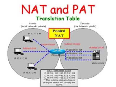
Static NAT – It is one-to-one mapping of a private IP address to a public IP address. Static NAT is useful when a network device inside a private network needs to be accessible from internet.
Dynamic NAT – It can be stated as mapping of a private IP address to a public IP address from a group of public IP addresses called as NAT pool. Dynamic NAT institutes a one-to-one mapping between a private IP address to a public IP address. Here the public IP address is taken from the group of IP addresses configured on the end NAT router.
Within NAT there are four IP address types:
- Inside local – Inside local address is an IP address assigned to a workstation inside our network.
- Inside global – Inside Global address are typically public IP addresses which are allocated to our end internet facing router to be used as the IP address for communicating with other devices in the internet.
- Outside local – This is the real IP address of the end device at other network.
- Outside global – This is the public IP address assigned to the end device on the other network to communicate other devices in the internet.
PAT – A private network may consist of many computers and there may be number of private networks in different organisations. We would soon run out of available IP addresses if we assign a public address to each system. In order to prevent this, we usually assign private addresses to the local network. These addresses can be redundant for different local networks i.e. many networks can have same private IP addresses. But when these network need to communicate through the internet, they need to have public IP addresses. This job is done by PAT. PAT (Port Address Translation) is very much similar to NAT. In this, multiple devices on a local area network (LAN) are mapped to a single public IP address.
NAT translates IP addresses only. PAT translates ports only, but is always used with NAT – never alone. NAT with PAT is also known as – NAPT (Network Address Port Translation) and may be used to allow many hosts to share a single IP address by multiplexing streams differentiated by TCP/UDP port numbers as well as IP addresses.
VLAN – A LAN (Local Area Network) is a group of computers in a network located in the same area. Every computer connected in a network receives a message broadcasted in a LAN. A need arise to leave certain devices or a group of devices from receiving certain information or to make a different group in the same network. Virtual Local Area Networks (VLANs) may achieve this.
It is a logical group of workstations, servers and network devices that appear to be on the same LAN despite their geographical distribution. The major advantage of VALN is that it allows network administrators to apply additional security to network communication.
VTP (VLAN Trunking Protocol) – It spreads the existence of Virtual Local Area Networks (VLAN) on the whole local area network. It is a Cisco proprietary protocol and is available on most of the Cisco Catalyst Family products. Usually the switches use VTP to communicate among themselves about VLAN configuration. It is a very useful protocol to create, manage and maintain a large network and can manage the addition, deletion, and renaming of VLANs without manual intervention. VTP configuration should be performed carefully ensuring that all switches are configured to prevent communication breakage in the network.
Managed and Unmanaged Switches – An unmanaged switch allows devices on an Ethernet network to communicate with each other. They are usually used in small networks. The major difference between managed and unmanaged switches is that unmanaged switches have a fixed configuration which is in built. Managed switches apart from having all the features of unmanaged switches, can be managed and configured and can monitor the LAN. It prioritise network traffic and manages available bandwidth while unmanaged switch cannot do so. They are accessed via a default web interface with a username and password.
Managed switches also provide port mirroring. Port Mirroring is also known as SPAN (Switched Port Analyser). Through this, network traffic can be monitored. In order to analyse and debug data or diagnose errors on a network, network administrators use port mirroring.
POE – With the use of Power Over Ethernet/Internet i.e. POE, one can minimise the number of wires required to configure a network by allowing the necessary electric current to be carried by the data cables rather than by power cords.